Showing posts with label watt. Show all posts

Tuesday, August 31, 2010

20VAC 60 Watt Sunrise Lamp Circuit.


Download this schematic diagram.


Datasheet semiconductor component.

1. LM324
2. IRF640
3. IRF740

In this circuit, a 120VAC lamp is slowly illuminated over a approximate 20 minute period. The bridge rectifier supplies 120 DC to the MOSFET and 60 watt lamp. A 6.2K, 5 watt resistor and zener diode is used to drop the voltage to 12 volts DC for the circuit power. The bridge rectifier should be rated at 200 volts and 5 amps or more. In operation, a 700 Hz triangle waveform is generated at pin 1 of the LM324 and a slow rising voltage is obtained at pin 8. These two signals are compared at pins 12 and 13 to produce a varying duty cycle rectangular waveform at pin 14, which controls the MOSFET and brightness of the 60 watt lamp. When power is applied, the lamp will start to illuminate within a minute or so, and will slowly brighten to full intensity in about 20 minutes. You can make that longer or shorter with adjustments to the 270K resistor at pin 9. The 2.2 ohm resistor and .015uF cap connected to the lamp serve to supress RFI. The diode at pin 9 and 10K resistor on pin 8 are used to discharge the 3300uF cap when power is removed. Power should be off for a few minutes before re-starting.

Caution: This circuit is connected directly to the AC line and presents a hazard if any part is touched while connected to the line. Use caution and do not touch any parts while the circuit is connected to the AC line. You may want to use a 9 volt battery connected across the 12 volt zener to check the basic operation. The DC voltage at pins 1,2,3,5,6,7 will all be around 4.3 volts if the circuit is working correctly. If the DC voltages are all correct, you can use a variac to slowly apply the full line voltage and check for proper operation.

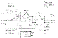
100 watt Hiwatt amplifier power supply schematic circuit diagram.


Download this schematic diagram.


Datasheet semiconductor component download.

1. TC9302
2. BYX94

Monday, August 2, 2010

1 Watt 2.45 GHz Linear Amplifier


Download this schematic diagram.


Download all parts component list.
Download datasheet semiconductor component. (PDF Format)

1. RF2126

Notes

Part numbers are for reference only. Alternate components may be substituted.

It's also possible to run the RF2126 at around 6.5 volts for slightly more power output. You could try a 7805 voltage regulator with two silicon diodes (or a red LED) in series with the ground lead (cathode to ground). Be sure to isolate the ground tab on the 7805 though or it won't work. You can even just use a plain old 7806 voltage regulator for 6 volts output.

Monday, July 6, 2009

25 Watt MosFet Audio Amplifier


Click here for download this schematic

Parts:

R1,R4_________47K 1/4W Resistors
R2____________4K7  1/4W Resistor
R3____________1K5 1/4W Resistor
R5__________390R 1/4W Resistor
R6__________470R 1/4W Resistor
R7___________33K 1/4W Resistor
R8__________150K 1/4W Resistor
R9___________15K 1/4W Resistor
R10__________27R 1/4W Resistor
R11_________500R 1/2W Trimmer Cermet
R12,R13,R16__10R 1/4W Resistors
R14,R15_____220R 1/4W Resistors
R17___________8R2 2W Resistor
R18____________R22 4W Resistor (wirewound)

C1___________470nF 63V Polyester Capacitor
C2___________330pF 63V Polystyrene Capacitor
C3,C5________470µF 63V Electrolytic Capacitors
C4,C6,C8,C11_100nF 63V Polyester Capacitors
C7___________100µF 25V Electrolytic Capacitor
C9____________10pF 63V Polystyrene Capacitor
C10____________1µF 63V Polyester Capacitor

Q1-Q5______BC560C 45V 100mA Low noise High gain PNP Transistors
Q6_________BD140 80V 1.5A PNP Transistor
Q7_________BD139 80V 1.5A NPN Transistor
Q8_________IRF530 100V 14A N-Channel Hexfet Transistor
Q9_________IRF9530 100V 12A P-Channel Hexfet Transistor

semiconductor list componen datasheet (PDF Format)

1. BC.560C
2. BD.140
3. BD.139
4. IRF.530
5. IRF.9530

Wednesday, May 20, 2009

2N3055 Simple inverter 5W

This simple inverter. The main aim of this circuit is to provide a suitable supply for all kind of low power battery chargers that normally connect to the mains such as mobile phones, electric shavers, etc, even an electronic neon light rated at 5W was successfully connected. Only easily obtainable components are used.


Download this schematic diagram.


Download list datasheet semiconductor parts. (PDF Format)

1. 2N3055

http://www.circuits-lab.com/

Monday, April 13, 2009

15 Watt Mini Amplifier

A 15 watt amplifier made using discrete components. Sergio designed this circuit for his Electronics Level II course.


Download this schematic diagram.


Download list datasheet semiconductor component. (PDF Format)

1. 2N3904
2. 2N2907A
3. 2N3906
4. IN4002


Notes:
This amplifier uses a dual 20 Volt power supply and delivers 15 watts RMS into an 8 ohm load. Q1 operates in common emitter, the input signal being passed to the bias chain consisting of Q8, Q9, D6, D13 and D14. Q8 and Q9 provide a constant current through the bias chain to minimize distortion, the output stage formed by a discrete darlington pair (Q2,Q4) and (Q7,Q11). The last two transistors are power Transitors, specifically the 2N3055 and MJ2955. The 7.02K resistor, R16 was made using a series combination of a 4.7K, 680 Ohms, and two 820 Ohms. The 1.1K resistor, R3 was made using a 100 Ohms and a 1K resistor. You can use this circuit with any walkman or CD player since it is designed to take a standard 500mv RMS signal.


http://www.zen22142.zen.co.uk/

100W Guitar Power Amplifier

The power amp board has remained unchanged since it was first published in 2002. It certainly isn't broken, so there's no reason to fix it. The photo below shows a fully assembled board (available as shown as M27). Using TIP35/36C transistors, the output stage is deliberately massive overkill. This ensures reliability under the most arduous stage conditions. No amplifier can be made immune from everything, but this does come close.


Download this image.


The power amp (like the previous version) is loosely based on the 60 Watt amp previously published (Project 03), but it has increased gain to match the preamp. Other modifications include the short circuit protection - the two little groups of components next to the bias diodes (D2 and D3). This new version is not massively different from the original, but has adjustable bias, and is designed to provide a "constant current" (i.e. high impedance) output to the speakers - this is achieved using R23 and R26. Note that with this arrangement, the gain will change depending on the load impedance, with lower impedances giving lower power amp gain. This is not a problem, so may safely be ignored.

Should the output be shorted, the constant current output characteristic will provide an initial level of protection, but is not completely foolproof. The short circuit protection will limit the output current to a relatively safe level, but a sustained short will cause the output transistors to fail if the amp is driven hard. The protection is designed not to operate under normal conditions, but will limit the peak output current to about 8.5 Amps. Under these conditions, the internal fuses (or the output transistors) will probably blow if the short is not detected in time.


Download this schematic diagram.


Download datasheet semiconductor component. (PDF Format)

1. BC559

2. BC549

3. BD139

4. BD140

5. TIP35C

6. TIP36C


Monday, March 30, 2009

Power supply for the 40 W single chip amplifier.

Constructing the power supply for this amplifier is simple. As shown on the schematic above you need to wire up a 18-0-18 (center tapped) transformer in order to get the recommended +/- 25V. Be very careful since this construction involves mains wiring.

1-chip 40 watt amplifier.

This is a compact, easy to build amplifier that uses one IC only but delivers 40 watts of audio power. It is ideal for amplifying audio from your mobile CD player or iPod. The chip being used here is the TDA1514 originally brought to the market by Phillips/Valvo. The best characteristics of this chip is its high output power and robustness. It is available in a 9-pin SIL plastic package with a metal mount.

Its package has a heat resistance of less than 1.5K/W. This means that the heatsink must have a heat resistance of only 3.8K/W when the chip reaches its maximum power dissipation of 19W (at Ub = +/-27.5V, Tu = 500C).
One can see from the diagram that only a handful of passive elements are needed to build the chip into a powerful audio amplifier. The power supply as supplied must be able to deliver a current of at least 3 amperes. The standby current consumption is about 60 mA. The supply voltage must never go beyond 27.5 volts!

In building the circuit, keep the wires to the power supply and outputs as short as possible. The resistos R4 and R5 set the voltage gain at the feedback which, in this case, is between 20 and 46 dB.
For a single channel amplifier(mono), a 80 VA transformer (T1) should be sufficient. If you construct two channels (or stereo) amps, 120 VA is recommended. Capacitors Cx and Cy should be at least 4.700uF rated at 35V. It can be up to 10.000uF. Capacitors twice as large discharge slower giving better peak power potential resulting to better power output. Feel free to increase the capacitance but take note that you may not get much additional benefit for the price involved. Make sure they are connected the right way around too or they will blow and cause injury.


Download this schematic diagram.


Semiconductor datasheet component. (PDF Format)

1. TDA 1514