Showing posts with label circuits. Show all posts

Thursday, September 2, 2010

170W Audio Power Amplifier.


Download this schematic diagram.

Download part list component.


Datasheet semiconductor component.

1. NE5534

2. MJE350

3. MJE340

4. BD139

5. BC546B

6. BC556B

7. MJE15030

8. MJE15031

9. MJE15003

10. MJE15004

11. BAT85

12. IN4004

13. BY254

The circuit is being powered by two 15V power supply for each channel, that is regulated by the combination of resistors R7-9 and Zener diodes D1-2. The frequency bandwidth is limited to a specific value due to the presence of low pass filter from R2 & C2 and high pass filter from R3 & C1. The total feedback of the circuit is concentrated on the positive non-inverting input of the IC1 that functions as differential amplifier. The node of R4-5 is applied with the feedback voltage from the output through R6. The current regulated by R10 & R14 across Q1-2 is 10mA as they operate in class A while in class AB, the power transistors Q8-11 operate in the output with a regulated constant current of 100mA each power transistor, done by trimmer TR1 and Q3. This will match the voltage drop at 27mV, higher than the provided voltage of R25-28.

A heatsink with sufficient dimension to provide cooling is placed above Q1-2-3-6-7 to maintain the possible thermic stability while the protection from reverse voltages from the load is performed by diodes D9-10.Additional fan can also be employed to suppress high temperature for efficient operation. The stability during high frequencies is sustained by the Zobel network consisting of R29 & C18. Due to capacitive load, the amplifier output is protected by a 1mm diameter 15-coil inductor L1 with R30 for square pulses passage.

Each power amplifier that is created will correspond to a transformer to handle large capacitors and provide proportional power. The transformer input is connected to the AC line which can incorporate delay circuit for protection from excessive supply. The cables that would carry the current to the amplifier should be appropriate enough.

Tuesday, August 31, 2010

88-108 MHz FM Broadcast Transmitter Circuit.


Download this schematic diagram.


Datasheet semiconductor component.

1. NE555
2. 2N4392

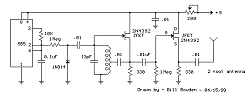
This circuit will transmit a continuous audio tone on the FM broadcast band (88-108 MHz) which could used for remote control or security purposes. Circuit draws about 30 mA from a 6-9 volt battery and can be
received to about 100 yards. A 555 timer is used to produce the tone (about 600 Hz) which frequency modulates a Hartley oscillator. A second JFET transistor buffer stage is used to isolate the oscillator from the antenna so that the antenna position and length has less effect on the frequency. Fine frequency adjustment can be made by adjusting the 200 ohm resistor in series with the battery. Oscillator frequency is set by a 5 turn tapped inductor and 13 pF capacitor. The inductor was wound around a #8 X 32 bolt (about 3/16 diameter) and then removed by unscrewing the bolt. The inductor was then streached to about a 3/8 inch length and tapped near the center. The oscillator frequency should come out somewhere near the center of the band (98 MHz) and can be shifted higher or lower by slightly expanding or compressing the inductor. A small signal diode (1N914 or 1N4148) is used as a varactor diode so that the total capacity in parallel with the inductor varies slightly at the audio rate thus causing the oscillator frequency to change at the audio rate (600 Hz). The ramping waveform at pins 2 and 6 of the timer is applied to the reversed biased diode through a large (1 Meg) resistor so that the capacitance of the diode changes as the ramping voltage changes thus altering the frequency of the tank circuit. Alternately, an audio signal could be applied to the 1 Meg resistor to modulate the oscillator but it may require an additional pullup resistor to reverse bias the diode. The N channel JFET transistors used should be high frequency VHF or UHF types (Radio Shack #276-2062 MPF102) or similar.

100 watt Hiwatt amplifier power supply schematic circuit diagram.


Download this schematic diagram.


Datasheet semiconductor component download.

1. TC9302
2. BYX94

Sunday, August 1, 2010

Fire Alarm Circuit Using LDR


Download this schematic diagram.


Download datasheet semiconductor component. (PDF Format)

1. LM7805

2. IN4007

3. BC107

4. UM66

5. TDA2002

Here is a simple fire alarm circuit based on a LDR and lamp pair for sensing the fire.The alarm works by sensing the smoke produced during fire.The circuit produces an audible alarm when the fire breaks out with smoke.

When there is no smoke the light from the bulb will be directly falling on the LDR.The LDR resistance will be low and so the voltage across it (below .6V).The transistor will be OFF and nothing happens.When there is sufficient smoke to mask the light from falling on LDR, the LDR resistance increases and so do the voltage across it.Now the transistor will switch to ON.This gives power to the IC1 and it outputs 5V.This powers the tone generator IC UM66 (IC2) to play a music.This music will be amplified by IC3 (TDA 2002) to drive the speaker.

The diode D1 and D2 in combination drops 1.4 V to give the rated voltage (3.5V ) to UM66 .UM 66 cannot withstand more than 4V.
* The speaker can be a 8Ω tweeter.
* POT R4 can be used to adjust the sensitivity of the alarm.
* POT R3 can be used for varying the volume of the alarm.
* Any general purpose NPN transistor(like BC548,BC148,2N222) can be used for Q1.
* The circuit can be powered from a 9V battery or a 9V DC power supply.
* Instead of bulb you can use a bright LED with a 1K resistor series to it.

Monday, July 6, 2009

25 Watt MosFet Audio Amplifier


Click here for download this schematic

Parts:

R1,R4_________47K 1/4W Resistors
R2____________4K7  1/4W Resistor
R3____________1K5 1/4W Resistor
R5__________390R 1/4W Resistor
R6__________470R 1/4W Resistor
R7___________33K 1/4W Resistor
R8__________150K 1/4W Resistor
R9___________15K 1/4W Resistor
R10__________27R 1/4W Resistor
R11_________500R 1/2W Trimmer Cermet
R12,R13,R16__10R 1/4W Resistors
R14,R15_____220R 1/4W Resistors
R17___________8R2 2W Resistor
R18____________R22 4W Resistor (wirewound)

C1___________470nF 63V Polyester Capacitor
C2___________330pF 63V Polystyrene Capacitor
C3,C5________470µF 63V Electrolytic Capacitors
C4,C6,C8,C11_100nF 63V Polyester Capacitors
C7___________100µF 25V Electrolytic Capacitor
C9____________10pF 63V Polystyrene Capacitor
C10____________1µF 63V Polyester Capacitor

Q1-Q5______BC560C 45V 100mA Low noise High gain PNP Transistors
Q6_________BD140 80V 1.5A PNP Transistor
Q7_________BD139 80V 1.5A NPN Transistor
Q8_________IRF530 100V 14A N-Channel Hexfet Transistor
Q9_________IRF9530 100V 12A P-Channel Hexfet Transistor

semiconductor list componen datasheet (PDF Format)

1. BC.560C
2. BD.140
3. BD.139
4. IRF.530
5. IRF.9530

6 Input Mixer


A simple mixer with 3 line inputs and 3 mic inputs using commonly available parts.


click here for download this schematic diagram


The mixer circuit above has 3 line inputs and 3 mic inputs. The mic inputs are suitable for low impedance 200-1000R dynamic microphones. An ECM or condenser mic can also be used, but must have bias applied via a series resistor. As with any mixer circuit, a slight loss is always introduced. The final summing amplifier has a gain of 2 or 6dB to overcome this. The Input line level should be around 200mV RMS.

The mic inputs are amplified about 100 times or 40dB, the total gain of the mixer including the summing amplifier is 46dB. The mic input is designed for microphones with outputs of about 2mV RMS at 1 meter. Most dynamic microphones meet this standard.

The choice of op-amp is not critical in this circuit. Bipolar, FET input or MOS type op-amps can therefore be used; i.e 741, LF351, TL061, TL071, CA3140 etc. The power supply is a dual positive and negative supply, two 9 Volt batteries may be used as shown above or a power supply is recommended for longer periods of use.

Download list datasheet semiconductor component. (PDF Format)

1. LM741

2. LM324

3. LF351

4. NE5534

5. TL071

Wednesday, May 20, 2009

LM2577 5V to 12V DC Converter step up Voltage Regulator

DC to DC step up voltage regulator. Wide input voltage 3.5Vdc to 40Vdc. This is Circuit DC to DC converter step up vol


Download this schematic.


Download list semiconductor datasheet. (PDF Format)

1. LM2577
2. IN5821

http://www.circuits-lab.com/

Nagative voltage generation using 555 timer

This 555 timer based PWM controller features almost 0..100% pulse width regulation using R1, while keeping the oscillator frequency relatively stable. The frequency is dependent on values of R1 and C1, values shown will give a frequency range from about 170 to 200 Hz. Any 555 chip will do, CMOS is fine as well. Diodes are not critical, I used 1N4148. Total cost of parts is about $2. As the whole thing is quite trivial, it’s very easy to build on prototyping board like I did.


Download this schematic diagram.


Download semiconductor datasheet parts. (PDF Format)

1. NE555

2. BD140


PWM Speed Motor Controller By IC 555-Electronic control circuit - [Link]

Monday, April 20, 2009

12 Volt 30 Amp Power Supply


Download this schematic diagram.


Download list datasheet semiconductor parts. (PDF Format)

1. TIP2955
2. LM7812


Description

Using a single 7812 IC voltage regulator and multiple outboard pass transistors, this power supply can deliver output load currents of up to 30 amps. The design is shown below:

The input transformer is likely to be the most expensive part of the entire project. As an alternative, a couple of 12 Volt car batteries could be used. The input voltage to the regulator must be at least several volts higher than the output voltage (12V) so that the regulator can maintain its output. If a transformer is used, then the rectifier diodes must be capable of passing a very high peak forward current, typically 100amps or more. The 7812 IC will only pass 1 amp or less of the output current, the remainder being supplied by the outboard pass transistors. As the circuit is designed to handle loads of up to 30 amps, then six TIP2955 are wired in parallel to meet this demand. The dissipation in each power transistor is one sixth of the total load, but adequate heat sinking is still required. Maximum load current will generate maximum dissipation, so a very large heat sink is required. In considering a heat sink, it may be a good idea to look for either a fan or water cooled heat sink. In the event that the power transistors should fail, then the regulator would have to supply full load current and would fail with catastrophic results. A 1 amp fuse in the regulators output prevents a safeguard. The 400mohm load is for test purposes only and should not be included in the final circuit.

for detail, pleace click here

0 - 300V Adjustable Power Supply.


Download this schematic.


Download datasheet semiconductor parts. (PDF Format)

1. BUZ326
2. BC547

Introduction

To prevent my high voltage experiments to go up in smoke completely, I designed
a simple circuit which can provide an adjustable voltage source of 0 to 330 Volt..
The supply is short-ciruit proof: the current is limited to about 100mA.

Circuit description

TR1 is a 1:1 mains transformer; it is included for safety.

The mains voltage from TR1 is rectified with bridge D1 (1Amp / 500V) and large elcap C1.

T1 is switched as a source follower: the source of T1 will follow the voltage of the
wiper of R3. D2 is included to protect the gate of T1; although in theory not necessary
I strongly recommend to include it!

T2 and shunt resistor R2 build the current limiter. When the output current becomes too high, T2 will discharge
the gate of T1. This will prevent the current to become too high.
The value of R3 has been determined experimentally; it depends also on the Hfe of T2 so you may need to tune the value of R2.

Note that T1 needs a large heatsink: in worst case T1 will dissipate 330V x 100mA = 33Watt!
Instead of a BUZ 326 (400V/10.5Amp) you can also use an IRF740 (400V/10Amp).
The output impedance of the power supply is determined by the beta of T1, so the larger the MOSFET
the lower the output impedance!


Sunday, April 5, 2009

Flashing Heart Circuit

This is LED flashing circuit, the circuit is quite simple. Alternatively, you could be create another shape, not just heart shape.


Download this schematic.


Component list:

Resistors
R1, R2 - 470 ohm, 1/2-watt
R3-R5 - 100 ohm, 3-watt
R6-R8 - 1000 ohm, 1.4-watt
R9 - 5000 ohm potentiometer


Capacitors
C1, C2 - 100uF, 16 volts, electrolytic radial


Semiconductors
IC1 - 4047, low power monostable/astable multivibrator
Q1-Q3 - 2n3643 NPN transistor or equivalent

Download datasheet
semiconductor
component:

1. 4047
2. 2N3643


Diodes

LED1-LED84 - yellow light-emitting diode
LED85-LED126 - red light-emitting diode
LED127-LED142 - green light-emitting diode


Other components
PS1 - 12VDC @ 500mA wall transformer


Miscellaneous: Jumper wire, solder, printed circuit board,
drill and bits,14 pin I.C. socket, and a frame or case.

Saturday, March 14, 2009

Current Expanded Regulated Power Supply

Actually, this is ordinary regulated power supply, but the current expander using a transistor make this power supply become powerful.

Based on the datasheet, the stabilizer IC’s can deliver up to 1A output current. For example 78xx series regulators are available in different voltage ratings, but in any case the current should not exceed 1A.

The transistor Q1 (2N 29055) used here has 5A current capacity. The resistor R1 is used to keep the current through regulator IC below 300mA. When the current through R1 increases the base current of Q1 (2N 29055) also increases & the load required load current flows through this transistor. By this way a current greater than the capacity of the regulator IC can be delivered to the load. The C1 is used to filter the ripples off the rectifier output.


Download this schematic diagram.


Notes:

  1. Assemble the circuit on good quality PCB.
  2. T1 can be a 230V primary,15V/1A secondary, step down transformer.
  3. If 1 A bridge is not available, make one using four 1N 4007 diodes.
  4. The series regulator IC should be selected according to the desired output voltage.
  • IC 7805 for 05V
  • IC 7806 for 06V
  • IC 7809 for 09V
  • IC 7812 for 12V
Semiconductor datasheet download. (PDF Format)

1. LM78XX
2. 2N2955

Friday, March 13, 2009

Power Supply 1.3 - 32 V / 5A with Short Circuit Protection

This is a very easy to build power supply that is based on LM338 5A adjustable voltage regulator. I am using the supply for a long time, have no problem yet. Only current adjust is missing but I overcome this situation by using an LCD panel ampermeter. There is no PCB for the circuit. I took a 3x16 copper plate and strip the unused areas by a knife. If you want you can use analog meters instead of LCD panels.


Download this schematic diagram.


Download datasheet semiconductor component. (PDF Format)

1. LM338

2. IN4002

Notes:

  1. Use thick wires for connections.
  2. When connecting the LM338 to the heatsink use thermal paste.
  3. Use external supplies for LCD panels. They can be 9V batteries. The panels I use draws 1mA current and the batteries last sufficiently long time. If you have small transformers which can supply regulated 9V, you can use them. You need separate transformers for each panel!
  4. The transformer should be 100 Watt but if you don't need high current you can try transformers that you already have. (I can draw 6A from 100Watt transformer.)
  5. If you have multi winding transformer you can use the diode connections shown in schematic. Diodes must be 10-15 A.
  6. Be careful while connecting LM338. Don't put it inverse.
  7. Output of your transformer mustn't exceed 25V AC...