In order to obtain a good audio reproduction at different listening levels, a different tone-controls setting should be necessary to suit the well known behaviour of the human ear. In fact, the human ear sensitivity varies in a non-linear manner through the entire audible frequency band, as shown by Fletcher-Munson curves.
A simple approach to this problem can be done inserting a circuit in the preamplifier stage, capable of varying automatically the frequency response of the entire audio chain in respect to the position of the control knob, in order to keep ideal listening conditions under different listening levels.
Fortunately, the human ear is not too critical, so a rather simple circuit can provide a satisfactory performance through a 40dB range.
The circuit is shown with SW1 in the "Control-flat" position, i.e. without the Automatic Loudness Control. In this position the circuit acts as a linear preamplifier stage, with the voltage gain set by means of Trimmer R7.
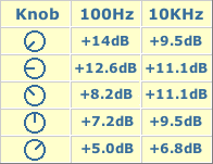
Switching SW1 in the opposite position the circuit becomes an Automatic Loudness Control and its frequency response varies in respect to the position of the control knob by the amount shown in the table below.
C1 boosts the low frequencies and C4 boosts the higher ones. Maximum boost at low frequencies is limited by R2; R5 do the same at high frequencies.
Technical data:
Frequency response referred to 1KHz and different control knob positions:
Total harmonic distortion at all frequencies and 1V RMS output: <0.01%
Notes:
- SW1 is shown in "Control flat" position.
- Schematic shows left channel only, therefore for stereo operation all parts must be doubled except IC1, C6 and C8.
- Numbers in parentheses show IC1 right channel pin connections.
- R7 should be set to obtain maximum undistorted output power from the amplifier with a standard music programme source and P1 rotated fully clockwise.