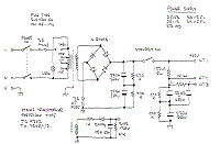
Download this schematic diagram.
Datasheet semiconductor component download.
1. TC9302
2. BYX94

Notes
Part numbers are for reference only. Alternate components may be substituted.
It's also possible to run the RF2126 at around 6.5 volts for slightly more power output. You could try a 7805 voltage regulator with two silicon diodes (or a red LED) in series with the ground lead (cathode to ground). Be sure to isolate the ground tab on the 7805 though or it won't work. You can even just use a plain old 7806 voltage regulator for 6 volts output.

This array charger ambit is advised for recharging NiCad batteries based on an AC-powered accepted antecedent method. It can crank out as abundant as 1 amp and can be adapted to go alike college by allotment altered accessories for Q1. Since this ambit uses AC band voltages and currents, amuse exercise acute attention during assembly, turn-on, and test. NiCAD batteries accept a accommodation blueprint alleged milliamp-hours. This amount alleged “C” is a admeasurement of how abundant absolute accepted they can accommodate in one hour. Milliamp-hours is addition way to accurate the activity independent in the battery. To recharge a NiCAD array conservatively, it is accepted convenance to pump a accepted of 0.1 C into the anode or absolute terminal for about 12 hours. Therefore, if you had a D-size NiCAD with a accommodation of 4000mAh, you would appetite to allegation it at 400mA for about 12 hours. Addition advantage of this charging address is that it is affable on batteries and doesn’t account them to lose accommodation as bound as the fast allegation techniques.
The achievement accepted of this array charger ambit is controlled by the accretion of the bandgap advertence diode and the base-emitter alliance of the PNP transistor. The PNP transistor provides abrogating acknowledgment to the aboideau of the MOSFET. As acclaimed in the schematic, the batteries actuality answerable can accept a absolute of 12V which is agnate to about 8 NiCAD’s in series. The achievement accepted is bent by the amount of R1 which is bent by:
R1=3.2Volts/Iout
The ability amusement of R1 will equal:
Pr1=3.2Volts*Iout
Be abiding to accommodate pleanty of heatsink for Q1 and accept an appropriately sized resistor for R1. The afterward table summarizes some of the resistor accepted combinations that are possible:
Iout Resistor Amount Resistor Power
100mA 33 ohms 1 watt
500mA 6.2 ohms 2 watt
1Amp 3.3 ohms 5 watt

This is a similar circuit to the above and provides a 4 LED bar graph indicating the voltage of a common 3.6 volt Lithium – Ion recharable cell phone battery. The reference voltage is provided by a TL431 programmable voltage source which is set to 3.9 volts where the TL431 connects to the 1K resistor. The lower reference for the LED at pin 14 is set with the 5K adjustable resistor.
The programmed voltage of the TL431 is worked out with a voltage divider (10K 5.6K). The adjustment terminal or junction of the two resistors is always 2.5 volts. So, if we use a 10K resistor from the adjustment terminal to ground, the resistor current will be 2.5/10000 = 250uA. This same current flows through the upper resistor (5.6K) and produces a voltage drop of .00025 * 5600 = 1.4 volts. So the shunt regulated output voltage at the cathode of the TL431 will be 2.5 + 1.4, or 3.9 volts.
Working out the LED voltages, there are three 390 ohm resistors in series with another adjustable (5K) resistor at the bottom. Assuming the bottom resistor is set to 2K ohms, the total resistance is 390+390+390+2000 = 3170 ohms. So, the resistor current is the reference voltage (3.9) divided by the total resistance, or about 3.9/ (390 + 390 + 390 + 2000) equals 1.23 mA. This gives us about .00123*2000= 2.46 volts for the bottom LED, and about .00123*390 = .48 volts for each step above the bottom. So, the LEDs should light at steps of 2.46, 2.94, 3.42, and 3.9. A fully charged cell phone battery is about 4.2 volts. You can adjust the 5.6K resistor to set the top voltage higher or lower, and adjust the lower 5K resistor to set the bottom LED for the lowest voltage. But you do need a 6 to 12 volt or greater battery to power the circuit.